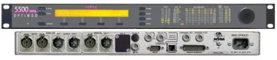
Optimod-FM 5500
| Harga | Rp 1,00 |
 |
Quality sound is what 5500 is all about—sound that attracts audiences by providing a polished, professional presentation regardless of format and source material. Exceptional versatility allows you to adjust the processor's audio texture to brand your audio, knowing that the resulting signature sound will remain consistent, cut-to-cut and source-to-source. Branding builds businesses and no other processors have the consistency to brand your sound like OPTIMOD.
The 5500's built-in stereo encoder, AES/EBU digital inputs and outputs, and analog I/O permit hasslefree interfacing to any broadcast plant, whether the 5500 is located at the studio or the transmitter. Tight band limiting to 15 kHz means you can use any uncompressed digital STL to pass 5500- processed audio from studio to transmitter without compromising on-air loudness - there's no need to use STL's having 44.1 or 48 kHz sample-rate.
Main Features:
• Five-band and two-band processing
• High performance stereo generator
• Cool running switching power supply
• Analog and AES3 digital I/O
Optimod-FM 5500: Specifications
System
- Frequency Response(Bypass Mode)
- Follows standard 50 µs or 75 µs pre-emphasis curve ±0.10 dB, 2.0 Hz - 15 kHz. Analog left/right output and digital output can be user-configured for flat or pre-emphasized output.
- Noise
- Output noise floor will depend upon how much gain the processor is set for (Limit Drive, AGC Drive, Two-Band Drive, and/or Multi-Band Drive), gating level, equalization, noise reduction, etc. The dynamic range of the A/D Converter, which has a specified overload-to-noise ratio of 110 dB, primarily governs it. The dynamic range of the digital signal processing is 144 dB.
- Total System Distortion
- (de-emphasized, 100% modulation) <0.01% THD, 20 Hz - 1 kHz, rising to <0.05% at 15 kHz. <0.02% SMPTE IM Distortion.
- Total System L/R Channel Separation
- >57 dB, 20 Hz - 15 kHz; 60 dB typical.
- Polarity
- (Two-Band and Bypass Modes): Absolute polarity maintained. Positive-going signal on input will result in positive-going signal on output.
- Processing Samplerate
- The 5500 is a "multirate" system, using internal rates from 32 kHz to 512 kHz as appropriate for the processing being performed. Audio clippers operate at 256 kHz (and are anti-aliased), while the composite limiter operates at 512 kHz.
In stand-alone stereo encoder mode, minimum samplerate is 64 kHz. - Processing Resolution
- Internal processing has 24 bit (fixed point) or higher resolution.
Analog Audio Input
- Configuration
- Stereo.
- Impedance
- >10 kΩ load impedance, electronically balanced.
- Nominal Input Level
- Software adjustable from -9 to +13 dBu (VU).
- Maximum Input Level
- +27 dBu.
- Connectors
- Two XLR-type, female, EMI-suppressed. Pin 1 chassis ground, Pins 2 (+) and 3 electronically balanced, floating and symmetrical.
- A/D Conversion
- 24 bit 128x oversampled delta sigma converter with linear-phase anti-aliasing filter. Converter outputs 64 kHz samplerate, which the 5500 then decimates to 32 kHz in DSP using an ultra-high-quality image-free synchronous samplerate converter. In strand-alone stereo encoder mode, 64 kHz output of converter is not downsampled.
- Filtering
- RFI filtered.
Analog Audio Output
- Configuration
- Stereo. Flat or pre-emphasized (at 50 µs or 75 µs), software-selectable.
- Source Impedance
- 50 Ω, electronically balanced and floating.
- Load Impedance
- 600 Ω or greater, balanced or unbalanced. Termination not required or recommended.
- Output Level
- (100% peak modulation): Adjustable from -6 dBu to +24 dBu peak, into 600 Ω or greater load, software-adjustable.
- Signal-to-Noise
- ≥90 dB unweighted (Bypass mode, de-emphasized, 20 Hz - 15 kHz bandwidth, referenced to 100% modulation).
- L/R Crosstalk
- ≤ -70 dB, 20 Hz - 15 kHz.
- Distortion
- ≤0.01% THD (Bypass mode, de-emphasized) 20 Hz - 15 kHz bandwidth.
- Connectors
- Two XLR-type, male, EMI-suppressed. Pin 1 chassis ground, Pins 2 (+) and 3 electronically balanced, floating and symmetrical.
- D/A Conversion
- 24 bit 128x oversampled, with high-pass filter at 0.15 Hz (-3 dB).
- Filtering
- RFI filtered.
Digital Audio Input
- Configuration
- Stereo per AES3 standard. Output configured in software as flat or pre-emphasized to the chosen processing pre-emphasis (50 µs or 75 µs), with or without J.17 pre-emphasis.
- Samplerate
- 32, 44.1, 48, 88.2 or 96 kHz, automatically selected.
- Connector
- XLR-type, female, EMI-suppressed. Pin 1 chassis ground, pins 2 and 3 transformer balanced and floating, 110 Ω impedance.
- Input Reference Level
- Variable within the range of -30 dBFS to -10 dBFS.
- J.17 De-emphasis
- Software-selectable.
- Filtering
- RFI filtered.
Digital Audio Output
- Configuration
- Stereo per AES3 standard. Output configured in software as flat or pre-emphasized to the chosen processing pre-emphasis (50 µs or 75 µs), with or without J.17 pre-emphasis.
- Samplerate
- Internal free running at 32, 44.1, 48, 88.2 or 96 kHz, selected in software. Can also be synced to the AES3 digital input at 32, 44.1, 48, 88.2 or 96 kHz, as configured in software.
- Word Length
- Software selected for 24, 20, 18, 16 or 14-bit resolution. First-order high-pass noise-shaped dither can be optionally added, dither level automatically adjusted appropriately for the word length.
- Connector
- XLR-type, male, EMI-suppressed. Pin 1 chassis ground, pins 2 and 3 transformer balanced and floating, 110 Ω impedance.
- Output Level
- (100% peak modulation): -20.0 to 0.0 dBFS software controlled.
- Filtering
- RFI filtered.
Composite Baseband Output
- Configuration
- Two outputs, each with an independent software-controlled output level control, output amplifier and connector.
- Source Impedance
- 0 Ω voltage source or 75 Ω, jumper-selectable.
- Load Impedance
- 37 Ω or greater. Termination not required or recommended.
- Maximum Output Level
- +16 dBu (8.72 Vp-p).
- Pilot Level
- Adjustable from 6.0% to 12.0%, software controlled.
- Pilot Stability
- 19 kHz, ±0.5 Hz (10 to 40 °C).
- D/A Conversion
- 24-bit.
- Signal-to-Noise Ratio
- ≥ 85 dB (Bypass mode, de-emphasized, 20 Hz - 15 kHz bandwidth, referenced to 100% modulation, unweighted).
- Distortion
- ≤ 0.02% THD (Bypass mode, de-emphasized, 20 Hz - 15 kHz bandwidth, referenced to 100% modulation, unweighted).
- Stereo Separation
- At 100% modulation = 3.5Vp-p, > 57 dB, 30 Hz - 15 kHz.
- Crosstalk-Linear
- ≤ -80 dB, main channel to sub-channel or sub-channel to main channel (referenced to 100% modulation).
- Crosstalk-Non-Linear
- ≤ -80 dB, main channel to sub-channel or sub-channel to main channel (referenced to 100% modulation).
- 38 kHz Suppression
- ≥ 70 dB (referenced to 100% modulation).
- 76 kHz & Sideband Suppression
- ≥ 80 dB (referenced to 100% modulation).
- Pilot Protection
- 60 dB relative to 9% pilot injection, ±250 Hz (up to 2 dB composite processing drive).
- Subcarrier Protection
(60-100 kHz) - ≥ 70 dB (referenced to 100% modulation; with up to 2 dB composite limiting drive; measured with 800 line FFT analyzer using "maximum peak hold" display).
- 57 kHz (RDS/RBDS)
Protection - 50 dB relative to 4% subcarrier injection, ±2.0 kHz
(up to 2 dB composite processing drive). - Connectors
- Two BNC, floating over chassis ground, EMI suppressed.
- Maximum Load Capacitance
- 0.047 µF (0 Ω source impedance). Maximum cable length of 100 ft / 30 m RG-58A/U.
- Filtering
- RFI filtered.
Subcarrier (SCA) Inputs
- Configuration
- Subcarrier inputs sum into composite baseband outputs before digitally controlled composite attenuator.
- Impedance
- > 600 Ω.
- SCA Sensitivity
- Variable from 220 mV p-p to >10 V p-p to produce 10% injection. Sensitivity is adjustable by an internal PC-board-mounted trim pot.
- Connectors
- Two BNC, unbalanced and floating over chassis ground, EMI suppressed.
- 19 kHz Pilot Reference
- SCA2 input can be re-jumpered to provide a 19 kHz pilot reference output.
Remote Computer Interface
- Supported Computer and Operating System
- IBM-compatible PC running Microsoft Windows® 2000/XP/Vista/7.
- Configuration
- TCP/IP protocol via direct cable connect, modem, or Ethernet interface. Suitable null modem cable for direct connect is supplied. Modem and other external equipment is not supplied.
- Serial Connector
- RS232 on DB-9 male connector, EMI-suppressed. Uses PPP to provide for direct or modem connection to the 8500 PC Remote application.
- Ethernet Connector
- Female RJ45 connector for 10 - 100 Mbps networks using CAT5 cabling. Native rate is 100 Mbps. Provides for connection to the 8500 PC Remote application through either a network, or, using a crossover Ethernet cable, directly to a computer.
- Ethernet Networking Standard
- TCP/IP.
Remote Control (GPI) Interface
- Configuration
- Eight (8) inputs, opto-isolated and floating.
- Voltage
- 6 - 15V AC or DC, momentary or continuous.
9 VDC provided to facilitate use with contact closure. - Connector
- DB-25 male, EMI-suppressed.
- Control
- User-programmable for any eight of user presets, factory presets, bypass, test tone, stereo or mono modes, analog input, digital input.
- Filtering
- RFI Filtering.
Tally Outputs
- Circuit Configuration
- Two NPN open-collector outputs.
- Voltage
- +15 volts maximum. Do not apply negative voltage. When driving a relay or other inductive load, connect a diode in reverse polarity across the relay coil to protect the driver transistors from reverse voltage caused by inductive kickback.
- Current
- 30 mA maximum.
- Indications
- Tally outputs can be programmed to indicate a number of different operational and fault conditions, including Input: Analog, Input: Digital, Analog Input Silent, AES Input Silent and AES Input Error.
Power
- Voltage
- 85 - 264 VAC, 50 - 60 Hz, 30 VA.
- Connector
- IEC, EMI-suppressed. Detachable 3-wire power cord supplied.
- Fuse
- 2.5A, 20mm Quick Acting HBC, mounted on the power supply circuit board.
- Grounding
- In order to meet EMI standards, circuit ground is hard-wired to chassis ground.
- Safety Standards
- ETL listed to UL standards, CE marked.
Environmental
- Operating Temperature
- 32 to 122 °F / 0 to 50 °C for all operating voltage ranges.
- Humidity
- 0 - 5% RH, non-condensing.
- Dimensions (W x H x D)
- 19" x 1.875" x 14.25" / 48.3 cm x 4.8 cm x 36.2 cm. One rack unit high.
- RFI / EMI
- Tested according to Cenelec procedures. FCC Part 15 Class A device.
- Shipping Weight
- 21 lbs. / 9.5 kg.