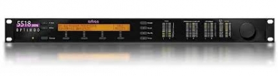
ORBAN Optimod-FM 5518
| Harga | Rp 1,00 |
 |
OPTIMOD-FM 5518 is a superb stand-alone stereo encoder combining look-ahead and bandlimited clipping techniques with latency as low as 2 ms and full overshoot limiting and extremely tight peak control in both the left/right and composite baseband domains, to control STL-induced overshoots while minimizing artifacts.
Optimod-FM 5518: Specifications
Frequency Response (Bypass Mode): Follows standard 50μs or 75μs pre-emphasis curve ±0.10 dB, 2.0 Hz–15 kHz. Analog left/right output and digital output can be user-configured for flat or preemphasized output.
Noise: <–85 dB below 100% modulation, 30-15,000 Hz, deemphasized.
Total System Distortion (de-emphasized, 100% modulation): <0.01% THD, 20 Hz–1 kHz, rising to <0.05% at 15 kHz. <0.02% SMPTE IM Distortion.
Total System L/R Channel Separation: >55 dB, 20 Hz – 15 kHz; 60 dB typical.
Polarity (Two-Band and Bypass Modes): Absolute polarity maintained. Positive-going signal on input will result in positive-going signal on output.
Processing Sample Rate: The 5518 is a "multirate" system, using internal rates from 64 kHz to 512 kHz as appropriate for the processing being performed. L/R overshoot limiters operate at 256 kHz (and are anti-aliased), while the composite limiter operates at 512 kHz.
Processing Resolution: Internal processing has 24 bit (fixed point) or higher resolution.
Installation
Analog Audio Input
Configuration: Stereo.
Impedance: >10kΩ load impedance, electronically balanced1.
Nominal Input Level: Software adjustable from –9.0 to +13.0 dBu (VU).
Maximum Input Level: +27 dBu.
Connectors: Two XLR-type, female, EMI-suppressed. Pin 1 chassis ground, Pins 2 (+) and 3 electronically balanced, floating and symmetrical.
A/D Conversion: 24 bit 128x oversampled delta sigma converter with linear-phase anti-aliasing filter.
Filtering: RFI filtered.
Analog Audio Output
Configuration: Stereo. Flat or pre-emphasized (at 50μs or 75μs), software selectable.
Source Impedance: 50Ω, electronically balanced and floating.
Load Impedance: 600Ω or greater, balanced or unbalanced. Termination not required or recommended.
Output Level (100% peak modulation): Adjustable from –6 dBu to +24 dBu peak, into 600Ω or greater load, software-adjustable.
Signal-to-Noise: >= 90 dB unweighted (Bypass mode, de-emphasized, 20 Hz–15 kHz bandwidth, referenced to 100% modulation).
L/R Crosstalk: <= –70 dB, 20 Hz–15 kHz.
Distortion: <= 0.01% THD (Bypass mode, de-emphasized) 20 Hz–15 kHz bandwidth.
Connectors: Two XLR-type, male, EMI-suppressed. Pin 1 chassis ground, Pins 2 (+) and 3 electronically balanced, floating and symmetrical.
D/A Conversion: 24 bit 128x oversampled, with highpass filter at 0.15 Hz (–3 dB).
Filtering: RFI filtered.
Digital Audio Input
Configuration: Stereo per AES3 standard, 24 bit resolution, software selection of stereo, mono from left, mono from right or mono from sum.
Sampling Rate: 32, 44.1, 48, 88.2, or 96 kHz, automatically selected.
Connector: XLR-type, female, EMI-suppressed. Pin 1 chassis ground, pins 2 and 3 transformer balanced and floating, 110Ω impedance.
Input Reference Level: Variable within the range of –30 dBFS to –10 dBFS.
J.17 Deemphasis: Software-selectable.
Filtering: RFI filtered.
Digital Audio Output
Configuration: Stereo per AES3 standard. Output configured in software as flat or pre-emphasized to the chosen processing pre-emphasis (50µs or 75µs), with or without J.17 pre-emphasis.
Sample Rate: Internal free running at 32, 44.1, 48, 88.2 or 96 kHz, selected in software. Can also be synced to the AES3 digital input at 32, 44.1, 48, 88.2 or 96 kHz, as configured in software.
Word Length: Software selected for 24, 20, 18, 16 or 14-bit resolution. First-order high-pass noiseshaped dither can be optionally added, dither level automatically adjusted appropriately for the word length.
Connector: XLR-type, male, EMI-suppressed. Pin 1 chassis ground, pins 2 and 3 transformer balanced and floating, 110Ω impedance.
Output Level (100% peak modulation): –20.0 to 0.0 dBFS software controlled.
Filtering: RFI filtered.
Wordclock/10 MHz Sync Reference Input
Configuration: Accepts 1x wordclock or 10 MHz reference signals, automatically selected. The DSP master clock can be phase-locked to these signals, which in turn phase-locks the 19 kHz pilot tone frequency, facilitating singe-frequency network operation. The digital output sample frequency can also be locked to these signals.
Level: Unit will lock to 1x wordclock and 10 MHz squarewaves and sinewaves having a peak value of 0.5 V to 5.0 V.
Connector: BNC female, grounded to chassis, non-terminating to allow reference signals to be looped through via an external BNC "tee" connector (not supplied).
Composite Baseband Output
Configuration: Two outputs, each with an independent software-controlled output level control, output amplifier and connector.
Source Impedance: 0Ω voltage source or 75Ω, jumper-selectable.
Load Impedance: 37Ω or greater. Termination not required or recommended.
Maximum Output Level: +16.0 dBu (13.82Vp-p).
Pilot Level: Adjustable from 6.0% to 12.0%, software controlled.
Pilot Frequency Stability: 19 kHz, ±1.0 Hz (10 degrees to 40 degrees C).
D/A Conversion: 24-bit
Signal-to-Noise Ratio: >= 85 dB (Bypass mode, de-emphasized, 20 Hz – 15 kHz bandwidth, referenced to 100% modulation, unweighted).
Distortion: <= 0.02% THD (Bypass mode, de-emphasized, 20 Hz – 15 kHz bandwidth, referenced to 100% modulation, unweighted).
Stereo Separation: > 55 dB, 30 Hz-15 kHz. 65 dB typical at 400 Hz.
Crosstalk-Linear: <= –80 dB, main channel to sub-channel or sub-channel to main channel (referenced to 100% modulation).
Crosstalk-Non-Linear: <= –80 dB, main channel to sub-channel or sub-channel to main channel (referenced to 100% modulation).
38 kHz Suppression: >= 70 dB (referenced to 100% modulation).
76 kHz & Sideband Suppression: >= 80 dB (referenced to 100% modulation).
Connectors: Two BNC, shell connected to chassis ground, EMI suppressed.
Maximum Load Capacitance: 0.047 µF (0Ω source impedance). Maximum cable length of 100 feet/30 meters RG–58A/U.
Filtering: RFI filtered.
Subcarrier (SCA) Inputs
Configuration: Two subcarrier inputs sum directly into composite baseband outputs; COMPx LVL control settings have no effect on the absolute subcarrier levels.
Impedance: 600Ω
SCA Sensitivity: Variable from <100 mV p-p to >10 V p-p to produce 10% injection assuming 100% modulation = 4 V p-p at the 5518's composite outputs.
Rear-panel accessible PC-board-mounted trim pots allow user to adjust the sensitivities of the two SCA inputs.
Connectors: Two BNC, shell connected to chassis ground, EMI suppressed.
19 kHz Pilot Reference: SCA2 input can be re-jumpered to provide a 19 kHz pilot reference output.
Remote Computer Interface
Supported Computer and Operating System: IBM-compatible PC running Microsoft Windows® 2000 (SP3 or higher), XP, Vista,7 or 8.
Configuration: TCP/IP protocol via direct cable connect, modem, or Ethernet interface. Suitable null modem cable for direct connect is supplied. Modem and other external equipment is not supplied. Serial Connector: RS–232 on DB–9 male connector, EMI-suppressed. Uses PPP to pro-vide for direct or modem connection to the 5518 PC Remote application.
Ethernet Connector: Female RJ45 connector for 10-100 Mbps networks using CAT5 cabling. Native rate is 100 Mbps. Provides for connection to the 5518 PC Remote application through either a network, or, using a crossover Ethernet cable, directly to a computer.
Ethernet Networking Standard: TCP/IP.
Remote Control (GPI) Interface
Configuration: Eight (8) inputs, opto-isolated and floating.
Voltage: 6–15V AC or DC, momentary or continuous. +12VDC provided to facilitate use with contact closure.
Connector: DB–25 male, EMI-suppressed.
Control: User-programmable for any eight of user presets, factory presets, bypass, test tone, stereo or mono modes, analog input, digital input.
Filtering: RFI filtered.
Tally Outputs
Circuit Configuration: Two NPN open-collector outputs.
Voltage: +15 volts maximum. Do not apply negative voltage. When driving a relay or other inductive load, connect a diode in reverse polarity across the relay coil to protect the driver transistors from reverse voltage caused by inductive kickback.
Current: 30 mA maximum
Indications: Tally outputs can be programmed to indicate a number of different operational and fault conditions, including Input: Analog, Input: Digital, Analog Input Silent, AES In-put Silent, and AES Input Error.
Power
Voltage: 85–264 VAC, 50–60 Hz, 30 VA.
Connector: IEC, EMI-suppressed. Detachable 3-wire power cord supplied.
Fuse: 2.5A 20mm Quick Acting HBC, mounted on the power supply circuit board.
Grounding: In order to meet EMI standards, circuit ground is hard-wired to chassis ground. To avoid ground loops, we recommend using an FM exciter with a balanced composite input.
Safety Standards: ETL listed to UL standards, CE marked.
Environmental
Operating Temperature: 32° to 122° F / 0° to 50° C for all operating voltage ranges.
Humidity: 0–95% RH, non-condensing.
Dimensions (W x H x D): 19" x 1.75" x 14.25" / 48.3 cm x 4.5 cm x 36.2 cm. One rack unit high.
Humidity: 0–95% RH, non-condensing.
RFI/EMI: Tested according to Cenelec procedures. FCC Part 15 Class A device.
Shipping Weight: 10 lbs / 4.6 kg